
What we built, why it is wired the way it is, and the pitfalls we met on the way — notes from a retrofit in Luxembourg
Summary. An existing Enphase installation (37 IQ8HC microinverters, 16.5 kWp DC, two IQ Battery 5P) was retrofitted with a three-phase Victron Energy Storage System: three MultiPlus-II 48/6500, an Ekrano GX, a Lynx DC backbone and 32 kWh of LFP storage (target 96 kWh). The Enphase side sits on the MultiPlus AC-out, which gives island operation and a black-start path, but also creates two energy-management systems that each believe they are in charge. This post describes the topology, the metering, how the two controllers were made to cooperate instead of trading energy with each other, why purely AC-coupled PV can leave the system in a black-start deadlock, and a catalogue of pitfalls with the adjustments that fixed them. It is written for enthusiasts who already know what an ESS assistant is and would rather not rediscover the same mistakes.
Disclaimer. This is a private build log, not an installation manual. AC work was carried out by a licensed electrician and grid registration handled by an installer. Grid codes, DSO rules and product firmware change; check the current manufacturer documentation and your DSO before copying anything here. The author accepts no liability — and neither, one suspects, would the manufacturers.
1. Starting point and goals
The house already had a well-behaved Enphase system: 37 panels on two roof planes (35° and 25°, facing south), each on an IQ8HC microinverter. The array is deliberately over-panelled — the panels are rated well above what the microinverters deliver — and each microinverter is capped at 330 W AC. That gives 37 × 330 W = 12.21 kW AC, which happens to equal the injection limit granted by the DSO (Creos) for this connection. Two Enphase IQ Battery 5P units (5 kWh each) were installed on phases L1 and L2; they charge from PV only.
What the Enphase system could not provide was large storage, backup power, three-phase balancing under our control, and peak shaving. The goals of the retrofit were therefore:
- Storage at scale — start with 32 kWh, grow to 96 kWh without redesigning the DC side.
- Island operation — keep the house and the PV running during a grid outage.
- Peak shaving — keep grid import under ~3 kW, the reference threshold for the capacity-based part of the tariff.
- Keep Enphase — no rip-and-replace of a working, warrantied PV system.
- Local control — everything readable and controllable on the LAN (openHAB), no cloud in the control path.
2. System overview
| Function | Component | Notes |
|---|---|---|
| Inverter/charger | 3× Victron MultiPlus-II 48/6500 | One per phase, VE.Bus; EN 50549-1 Type A+B certified |
| GX device | Ekrano GX | Venus OS, ESS assistant logic, DVCC |
| DC distribution | 2× Lynx Distributor (batteries), Lynx Shunt VE.Can, 1× Lynx Distributor (MultiPlus) | M8 terminals, 70 mm² cabling, 250 A fuse per MultiPlus |
| Storage | 2× EEL V6 Pro 48 V 16 kWh (LFP 16S, JK V19 BMS) | 32 kWh today, 6 packs / 96 kWh planned |
| Metering | 3× Victron VM-3P75CT | Roles: Grid, Loads, PV |
| PV | 37× Enphase IQ8HC, 16.5 kWp DC | 330 W AC cap each → 12.21 kW AC |
| AC-coupled storage | 2× Enphase IQ Battery 5P | L1 and L2 only, PV charging only |
| Automation | openHAB 5, MQTT, KNX, Modbus TCP | Dashboards, délestage, forecasts |
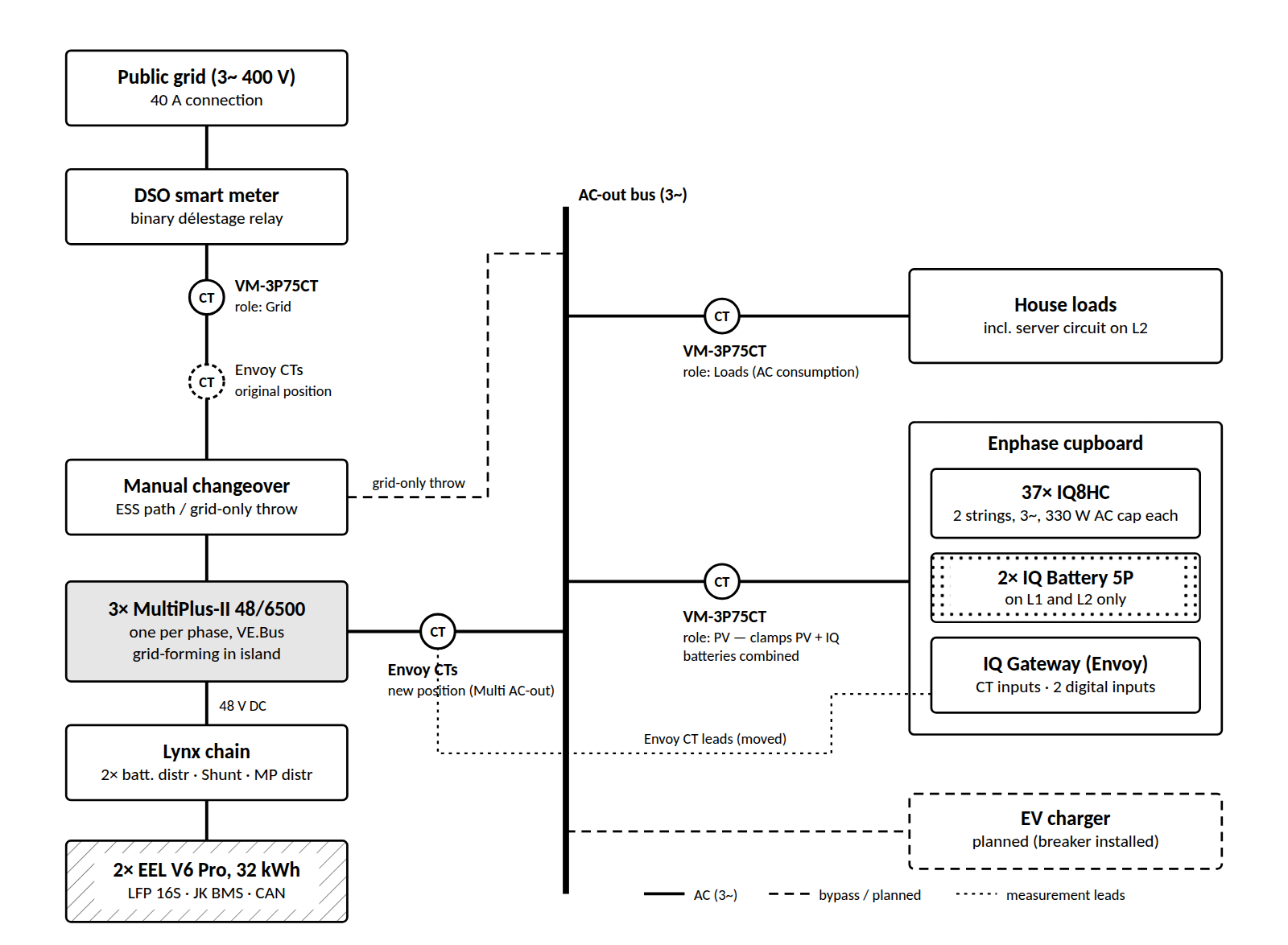
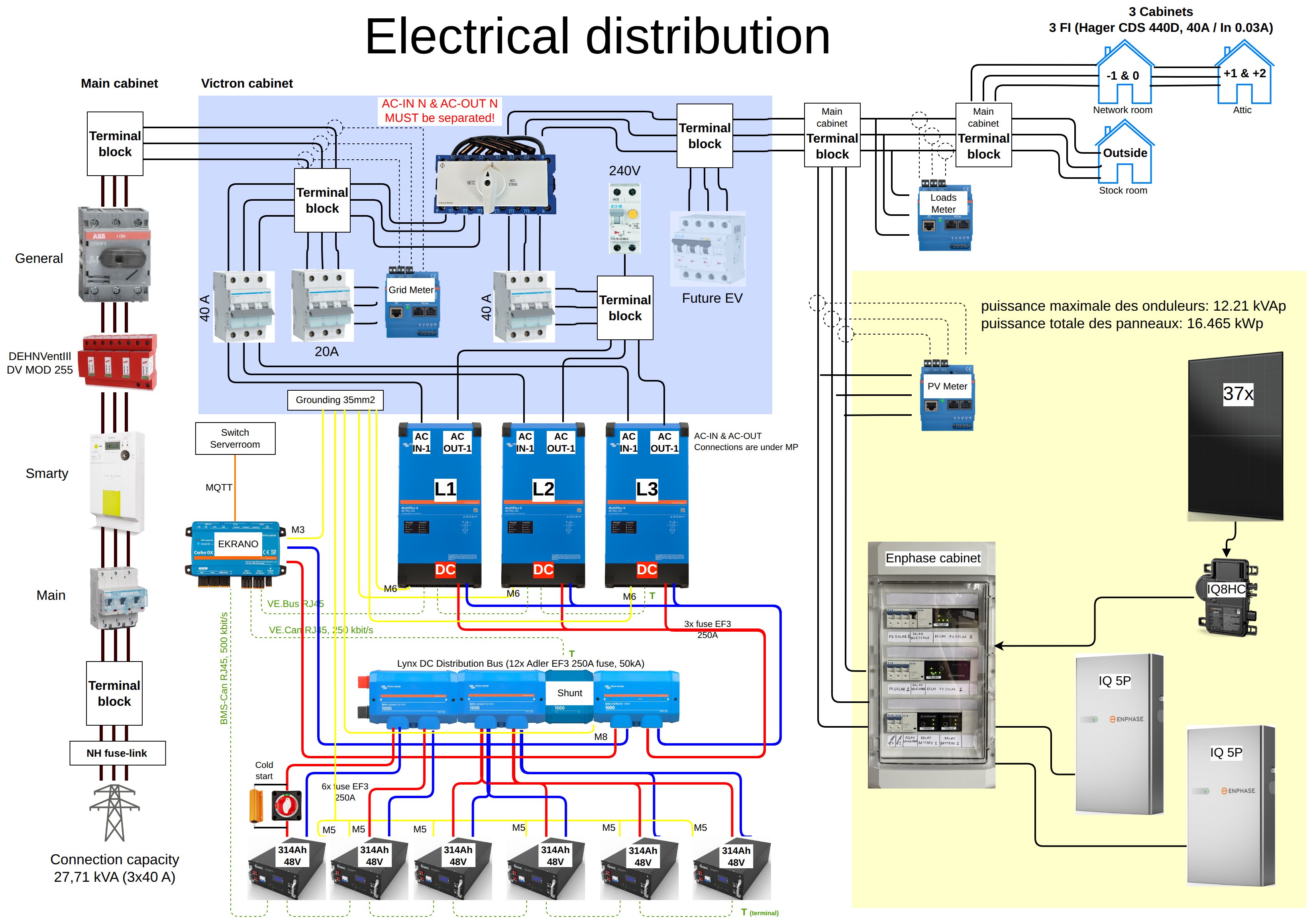
Figure 1 is deliberately simplified. Figure 2 shows the real thing: the main cabinet with the DSO meter and the general breaker, the Victron cabinet with its Netz / Notstrom changeover and the Grid meter, the Loads and PV meters, the Lynx DC bus and the separate Enphase cabinet. The red warning in the Victron cabinet is not decoration: the AC-in and AC-out neutrals of a MultiPlus must never be bridged, because in inverter mode the unit makes its own neutral–earth connection on AC-out.
2.1 Why the Enphase system sits on AC-out
Enphase and Victron both document this AC-coupling, and there are two places the PV could go. On AC-in (grid side of the MultiPlus) the PV behaves like any grid-tied inverter: simple, but the microinverters shut down whenever the grid does, so the house loses its solar exactly when it matters. On AC-out the MultiPlus forms the grid during an outage, the microinverters synchronise to it, and the MultiPlus throttles them through frequency shifting when the batteries are full (Section 5). We chose AC-out. Everything else in this document is, in some sense, the price of that decision.
2.2 Why MultiPlus-II and not Multi RS
The deciding factor was grid-code compliance: grid injection in Luxembourg requires EN 50549-1 certification including Type B behaviour, which the MultiPlus-II 48/6500 has and the Multi RS Solar did not suit. Secondary arguments were parallel/three-phase scalability, the low-frequency transformer (comfortable under long EV-charging loads) and full ESS assistant support. Neither device’s internal MPPT mattered here: all PV is AC-coupled.
2.3 Two sizing sanity checks
Victron’s AC-coupling guidance imposes two rules that are easy to skip because the system appears to work without them — until the first sunny day in island mode.
- Factor 1.0 rule. AC-coupled PV power must not exceed the continuous inverter/charger rating. The MultiPlus-II 48/6500 is rated 6 kW continuous at 25 °C, so three units give 18 kW against 12.21 kW of IQ8 output. Satisfied.
- Minimum battery capacity. For lithium, Victron asks for roughly 4.8 kWh of battery per 1.5 kWp of AC-coupled PV, i.e. about 39 kWh for 12.21 kW. With two packs (32 kWh) we are below that guideline; the IQ batteries do not count because they are not on the Victron DC bus. The third pack closes the gap. Until then, island operation on a sunny afternoon with full batteries is the scenario to watch. Not yet satisfied — known and accepted.
3. Metering architecture
Three VM-3P75CT meters are connected to the Ekrano, one per role: Grid (on the incoming feed), Loads (AC consumption downstream of the MultiPlus) and PV (the Enphase cupboard output). They connect over VE.Can or Ethernet; we gave them static addresses by MAC reservation on a dedicated VLAN. Two useful properties: several meters assigned to the same role are summed by the GX, and CT clamps may be stacked on one conductor as long as all cables pass in the same direction.
Why not use the Envoy as the PV source for Venus? The Envoy’s local API is fine for dashboards but poor for control: it adds latency, its per-phase granularity is limited, and it depends on a JWT token that expires. The ESS control loop therefore sees PV exclusively through the VM-3P75CT; Envoy data go to openHAB only.
Per-phase or total regulation? The Luxembourg smart meter bills on the sum of the three phases (netting across phases). Import on L3 while exporting on L1 costs nothing, so the ESS runs with grid-setpoint regulation on the total of all phases. This matters here because the IQ batteries only sit on L1 and L2: the phases are inherently asymmetric, and per-phase regulation would make the MultiPlus units fight that asymmetry for no financial gain.
What should the PV meter see? Originally the PV-role meter clamped only the two PV feeds from the roof, deliberately excluding the IQ batteries to obtain pure production data. The side effect: Venus booked IQ battery charging as house consumption, which made the AC Loads figure fiction on sunny days. We decided to re-clip the PV meter on the combined Enphase cupboard output (PV + IQ batteries). Venus now sees the net contribution of the Enphase subsystem and the Loads figure is real; pure PV production statistics come from a nightly Envoy export into openHAB instead.
4. Two controllers, one house: avoiding cross-charging
The Enphase gateway runs its own energy management. With consumption CTs on the grid feed it discharges the IQ batteries to push grid import to zero — which is exactly what the Victron ESS also tries to do. Two integrating controllers acting on the same error signal is a textbook recipe for oscillation, and in practice for cross-charging: the IQ batteries discharge, the Victron sees export and charges the EEL packs from them (or vice versa), and both round-trip losses are paid for nothing.
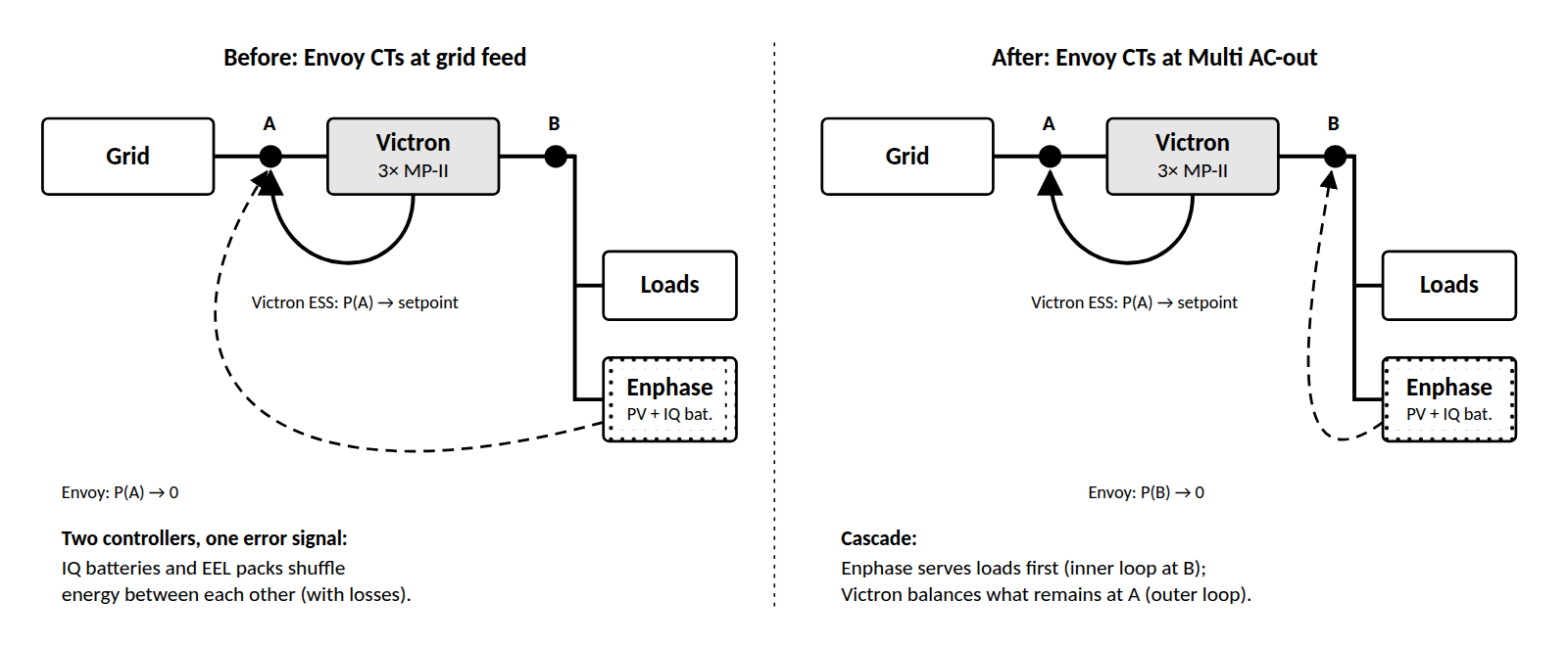
Our first instinct was to make Victron the master and demote the IQ batteries. We ended up with the opposite hierarchy, which is simpler to implement and uses the hardware more sensibly:
- The Envoy CTs are moved to the MultiPlus AC-out. From the Envoy’s point of view the MultiPlus now is the grid. The IQ batteries cover house loads first and absorb PV surplus first — an inner loop.
- The Victron ESS regulates the real grid connection — an outer loop that only sees what the Enphase side could not handle, and which alone decides about import, export and peak shaving.
A cascade with clearly separated measurement points is the classical way to make two controllers coexist; it behaves best when the inner loop is at least as fast as the outer one. We will report measured behaviour once the CTs have been moved. If you prefer Victron as master, the alternative is to curtail IQ battery discharge via Enphase’s own profile settings or via Node-RED logic — possible, but more moving parts.
5. Island operation, black start and the solar deadlock
5.1 Frequency shifting
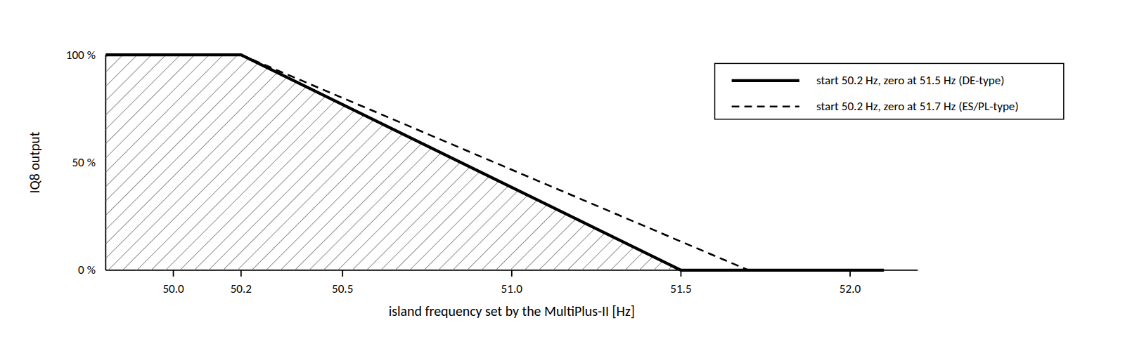
When the grid fails, the MultiPlus units open their transfer switches and form a three-phase island on AC-out. The IQ8 microinverters see a valid grid and keep producing; the IQ batteries synchronise as well. The only way the MultiPlus can tell the microinverters to back off — there is no communication link between the two worlds in this mode — is to raise the island frequency. The IQ8 grid profile contains an over-frequency power reduction (P(f)) curve, and the microinverters follow it.
5.2 Black start: automatic, but only with energy in the bank
The system is black-start capable in the sense that matters most: after a grid failure, or after the MultiPlus has shut down on low battery, it restarts without anyone touching it — provided the batteries still hold enough energy. The sequence is always the same: the DC bus is alive, the Ekrano and the MultiPlus units start, the MultiPlus forms the island, and after their grid-code reconnection delay the IQ8s synchronise and start producing. Every step depends on the one before it, and the first step depends on the battery.
That is the catch of AC-coupling. All 12.2 kW of PV in this house are grid-following: microinverters are required by their certification to stay silent when they see no grid (anti-islanding). They cannot create a grid; they can only join one. The IQ batteries do not help either — without Enphase’s own backup hardware they are grid-following as well. In this topology the only grid-forming device is the MultiPlus, and the MultiPlus runs on DC.
5.3 The deadlock
Imagine a long outage in winter: several grey days, loads that keep running, and the batteries eventually drained until the BMS opens. Now follow the chain (Figure 5): the DC bus is dead, so the MultiPlus cannot start; without the MultiPlus there is no island; without an island the IQ8s stay at 0 W, however bright the next morning is; and without PV nothing charges the batteries. A 16.5 kWp array on the roof, full sun, and not a single watt reaching the battery — the system is waiting for a condition that only it could create.
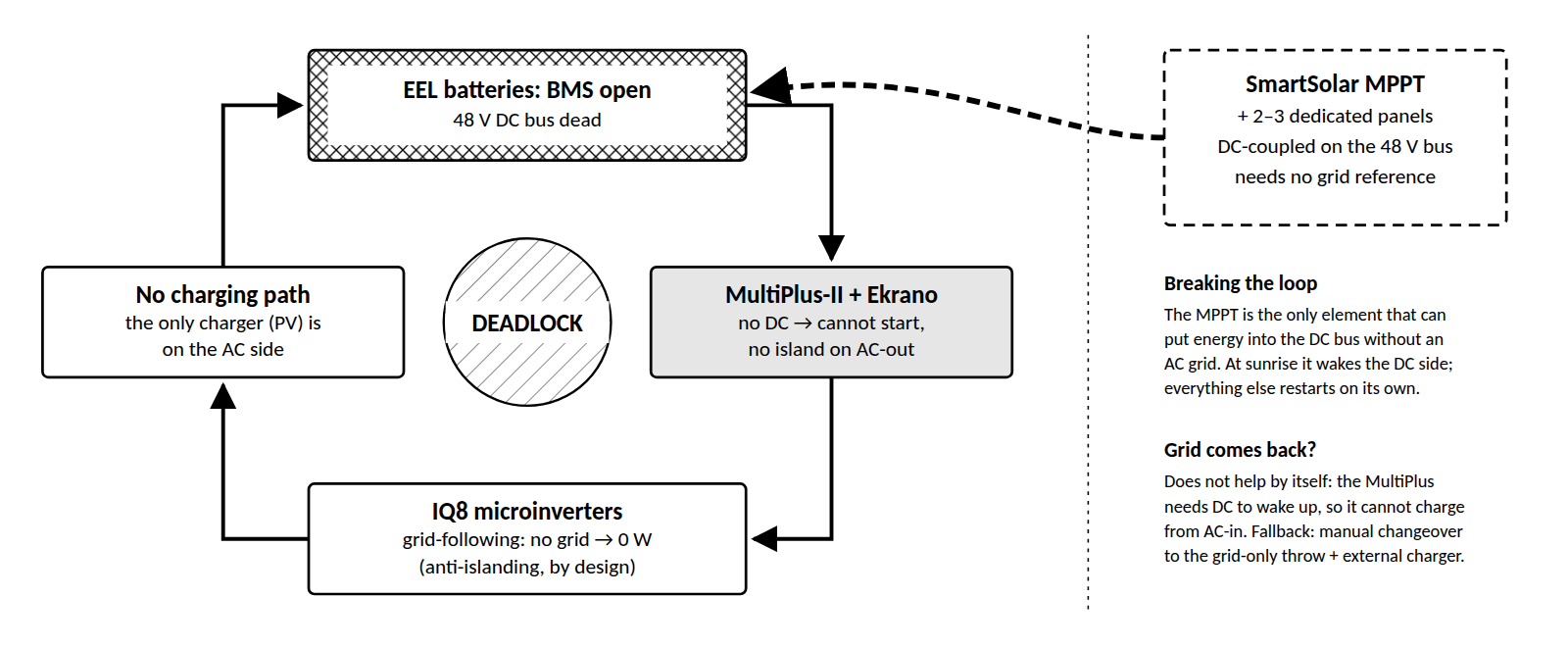
Two details make this worse than it first looks. First, the return of the grid does not end the deadlock automatically: the MultiPlus needs DC to wake up at all, so it cannot close its transfer switch and recharge from AC-in. Recovery then means switching the manual changeover to its grid-only throw (house supplied, batteries still dead) and recharging the bank with an external source — in our case the laboratory power supply that already served during commissioning. Second, lithium cells should not be left at 0 % for long; a deadlock that lasts days is a battery-health problem as well as a comfort problem.
5.4 First line of defence: never let the BMS decide
The cheapest fix is to make sure the BMS never has to act during an outage. The SoC strategy is therefore tiered:
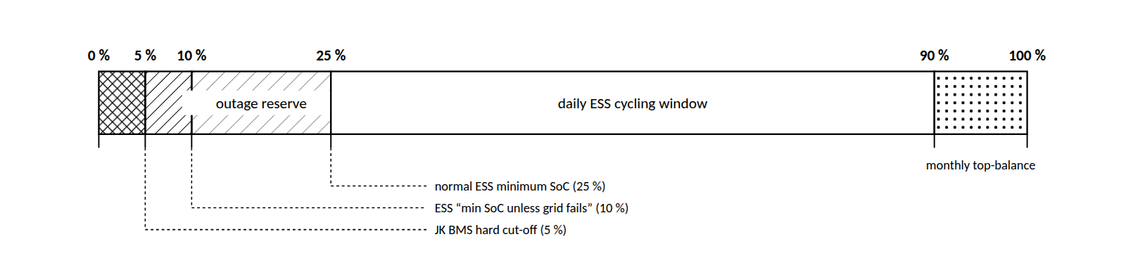
This covers ordinary outages. It does not cover the pathological ones: a multi-day outage with snow on the panels, a BMS trip for another reason (a cell over- or under-voltage, a temperature fault, a firmware hiccup), or simply the standby consumption of the DC-side electronics slowly eating the last 5 %. A tier is a policy; a deadlock needs a mechanism.
5.5 Future fix: a small DC-coupled solar charger [PLANNED]
The mechanism is a small, independent PV source that charges the 48 V bus directly: a Victron SmartSolar MPPT with two or three dedicated panels, connected to the Lynx chain with its own fuse. An MPPT charger is DC-coupled — it needs no AC grid reference — so it is the one element that can inject energy into the loop from outside. The recovery then runs on its own:
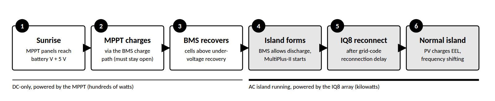
Points we will check before relying on it:
- The BMS must accept charge after a cut-off. FET-based BMSs such as the JK normally disable discharge on under-voltage but keep the charge path enabled; if the BMS powers itself down completely, the MPPT only feeds the bus side and step 2 fails. Verify your configuration, preferably on the bench.
- The MPPT must start from PV alone. Set the system voltage to a fixed 48 V rather than auto-detect — a dead bus gives no reference — and test a cold start with the battery disconnected. PV voltage must exceed battery voltage by about 5 V before a Victron MPPT starts converting.
- String voltage. A 100 V controller (e.g. 100/20) takes only two typical 400–450 W modules in series, and even that must be checked against open-circuit voltage at the coldest expected temperature. A 150 V controller (e.g. 150/35) allows three modules with typical Voc and more charge current; that is our preferred size.
- Winter yield. A 1 kWp mini-array delivers only a fraction of its rating on a grey December day. That is enough, because it only has to lift the cells above the BMS recovery threshold; the heavy lifting is done by the IQ8s once the island is up (step 5).
- Normal operation. DC-coupled PV does not count against the factor 1.0 rule, is controlled by DVCC like any Victron charger, and adds a little yield every day — a black-start insurance that pays a small dividend.
At a few hundred euros, removing the only failure mode that the system cannot recover from by itself is a reasonable insurance premium.
6. Délestage and export control
Luxembourg DSOs can send a load-management/curtailment signal (délestage) through the smart meter’s relay. That relay is purely binary: on or off. The DSO accepts a reduction to 30 % of output as a compliant response for systems able to modulate, and the IQ Gateway implements exactly that when a digital input is activated. The original installation instead used external relays that switched PV off completely — compliant, but wasteful.
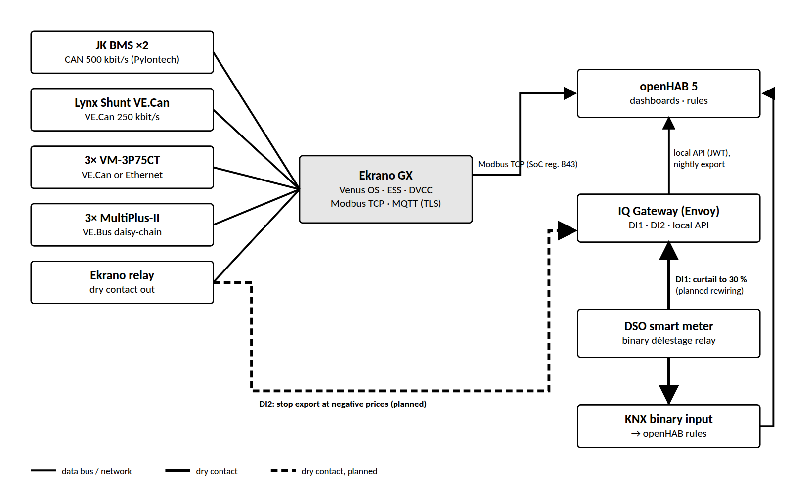
- DI1 — délestage (planned rewiring). The smart-meter relay goes directly to the gateway’s input; the old external relays become redundant.
- DI2 — negative prices (planned). An Ekrano relay will stop Enphase export when injection is worth less than nothing. Whether to limit export or production is still under discussion with the energy agency.
- Software alternative. Recent Enphase gateway firmware (≥ 8.2.4264) exposes SunSpec model 700 over Modbus TCP, including a power-limit enable and setpoint (registers 40310/40311), and Venus OS ≥ 3.60 can use it. We prefer the dry contacts because they keep working when the network does not, but the Modbus route is cleaner if you trust your LAN more than your relays.
7. Integration with openHAB
openHAB reads the Victron side over Modbus TCP from the Ekrano. Unit IDs (listed under Settings → Services → Modbus TCP → Available services) were 100 for system/ESS/Lynx Shunt, 225 for the JK BMS and 229 for the VE.Bus system. Battery SoC is register 843 on unit 100, an unsigned integer in percent without scaling. Enphase data come from the gateway’s local API with a JWT token; the only Envoy value used live is IQ battery SoC. Délestage state arrives via KNX.
A solar forecast rule runs each morning and will decide, the evening before, whether to sell battery energy overnight: only if tomorrow’s forecast refills the batteries. The forecast had one amusing bug, described in Section 8.
8. Pitfalls and adjustments
Each entry lists what we saw, what caused it, and what we changed. Status tags: [DONE] implemented, [DECIDED] agreed and being implemented, [PLANNED] not yet scheduled, [OPEN] unresolved.
8.1 Grid meter reading almost zero [DONE]
Symptom. The Grid-role VM-3P75CT showed near-zero power while the house was clearly importing.
Cause. The CTs sat between the manual changeover switch and its grid-only throw, i.e. on a conductor that carries no current in normal ESS operation.
Fix. Clamps moved upstream of the changeover switch. As a temporary workaround the grid meter was disabled and the ESS used the MultiPlus internal AC-in sensors, which is acceptable for control but useless for anything behind a bypass.
8.2 IQ and EEL batteries trading energy [DECIDED]
Symptom. Both energy-management systems reacting to the same grid measurement, with the risk of one battery system charging the other.
Cause. Envoy consumption CTs on the grid feed — see Section 4.
Fix. Envoy CTs moved to the MultiPlus AC-out, giving a cascade: Enphase inner loop, Victron outer loop.
8.3 “AC Loads” includes battery charging [DECIDED]
Symptom. Venus reported implausibly high house consumption on sunny days.
Cause. The PV-role meter excluded the IQ batteries, so their charging current appeared as load.
Fix. PV meter re-clipped on the combined Enphase output. Trade-off: raw PV production now comes from the Envoy export, not from Venus.
8.4 A circuit that bypasses the Loads meter [OPEN]
Symptom. Loads under-reported on L2.
Cause. The server circuit on L2 bypasses the Loads-role CT clamp.
Fix. Move the L2 clamp so it covers all house circuits. Meanwhile the servers are metered individually in openHAB. Lesson: walk every conductor from the AC-out terminal to the last breaker before trusting a Loads figure.
8.5 Per-phase regulation fighting an asymmetric system [DONE]
Cause. IQ batteries on L1/L2 only; per-phase grid setpoints make the MultiPlus units compensate an imbalance that the meter nets out anyway.
Fix. ESS set to regulate the total of all phases. Check your own meter’s billing method first — this is only correct if it nets across phases.
8.6 Island mode with too little battery [OPEN]
Cause. 32 kWh is below Victron’s ~39 kWh guideline for 12.2 kW of AC-coupled PV. In island mode with full batteries, frequency shifting must reduce the IQ8s before any cell reaches the BMS over-voltage limit.
Adjustment. Keep the daily ceiling at 90 % SoC, confirm the IQ8 P(f) curve, and add the third pack. Test a controlled island at high SoC on a sunny day with the electrician present — preferably not on the day of the family barbecue.
8.7 Cell over-voltage trips on first full charge [DONE]
Symptom. Both new packs tripped cell OVP (3.65 V) on their first charge to 100 %, with a cell spread of roughly 90–150 mV at the top of charge (one lagging cell on the first pack, two clusters on the second).
Cause. Most likely the factory state of balance of this batch; with a 3.00 V balance start and 2 A, the balancer could not close the gap before the leading cells hit the limit.
Fix. Each pack charged to 100 % individually before paralleling (avoids inrush between packs at different voltages). Balance start raised from 3.00 V to 3.40 V (Δ 10 mV, 2 A), charge target 3.45 V/cell (55.2 V), monthly top-balance to 100 %. This also matters for 8.6: an OVP disconnect in island mode is the worst possible moment.
8.8 Black-start deadlock after a BMS trip [PLANNED]
Symptom (anticipated). After a long outage drains the bank until the BMS opens, the system cannot restart — not with sunshine, and not even when the grid returns.
Cause. All PV is AC-coupled and grid-following; the only grid-forming device, the MultiPlus, needs DC to start (Section 5.3).
Fix. Tiered SoC limits so the ESS stops before the BMS has to (done); a manual recovery path via the grid-only throw and a bench supply (available); and in future a SmartSolar MPPT with 2–3 dedicated panels on the 48 V bus for autonomous black start (planned).
8.9 MQTT on the Ekrano refuses connections [DONE]
Symptom. Clients could not connect to port 1883.
Cause. With the local network security profile set to Secured, Venus only accepts MQTT over TLS on port 8883 and requires a non-empty username plus the password set under Access & Security (local network security profile). The same password also gates the local web UI.
Fix. Use 8883 with TLS and credentials — or use Modbus TCP, which is what we did for SoC.
8.10 Envoy token expiry [DONE]
Cause. Local API access to the IQ Gateway requires a JWT token with a limited lifetime; when it expires, dashboards silently freeze.
Fix. Keep the Envoy out of the control path entirely (Section 3), put the token expiry date in your calendar, and alarm on stale data in openHAB.
8.11 Three-phase configuration needs the whole chain [DONE]
Cause. An MK3-USB gives point-to-point access to one MultiPlus only; phase assignment requires all three units daisy-chained on VE.Bus.
Adjustment. Configure with the full VE.Bus chain and the GX connected. Much of the classic VEConfigure (Windows-only) work is unnecessary: ESS logic lives in the GX with DVCC, and VictronConnect runs natively on macOS.
8.12 DC side: shunt position and pre-charge [DONE]
Shunt. The Lynx Shunt must sit between all batteries and all loads: [Battery distributor 1] – [Battery distributor 2] – [Lynx Shunt] – [MultiPlus distributor]. Anything else and the SoC is computed from a fraction of the current.
Pre-charge. Three MultiPlus units hold a lot of DC-bus capacitance. The first battery connection was made through a battery switch bridged by a 47 Ω / 100 W resistor, then the switch was closed. Also: do not mix the 500 kbit/s BMS CAN and the 250 kbit/s VE.Can on one bus.
8.13 Solar forecast predicting a 5 PM sunset in September [DONE]
Symptom. Forecast of 9.8 kWh on a day that produced 71.2 kWh.
Cause. The sunset item supplied by the forecast binding was off by several hours (a UTC/local-time mislabelling); sunrise was correct, which made the bug harder to spot.
Fix. The rule computes sunrise/sunset locally with the NOAA solar-position formula and only logs the upstream value for comparison. Moral: in energy automation, time zones are a load-bearing component.
8.14 Binary délestage throws away 100 % of PV [PLANNED]
Cause. External relays switch PV off entirely, although 30 % curtailment is compliant.
Fix. Smart-meter relay rewired to the IQ Gateway input (Section 6). The signal remains binary — a granularity the author finds aesthetically offensive, but the DSO has not asked for his opinion.
9. Status and open items
| Item | Status |
|---|---|
| ESS connected and online with 2 packs (32 kWh) | [DONE] 24 Sep 2026 |
| Grid meter CT position | [DONE] |
| Envoy CTs to MultiPlus AC-out; PV meter on combined Enphase output | [DECIDED] |
| Loads CT on L2 to include server circuit | [OPEN] |
| Délestage relay → IQ Gateway DI1 (30 %) | [PLANNED] |
| Ekrano relay → IQ Gateway DI2 (negative prices) | [PLANNED] awaiting agency feedback |
| Controlled island test at high SoC | [OPEN] |
| Third to sixth battery pack | [PLANNED] |
| DC-coupled MPPT + 2–3 panels for autonomous black start | [PLANNED] future |
10. References
- Enphase Energy — AC-coupling with Victron battery inverters using Modbus TCP/IP, technical brief (EU; copy hosted by a third party).
- Enphase Energy — AC-coupling Enphase IQ Microinverters with Victron battery inverters, technical brief.
- Victron Energy — AC coupling and the Factor 1.0 rule.
- Victron Energy — MultiPlus-II 4k/4k5/6k5/10k 230 V manual (PDF), incl. technical specifications.
- Victron Energy — ESS design and installation manual.
- Victron Energy — VM-3P75CT Energy Meter manual (PDF).
- Victron Energy — GX Modbus-TCP manual; the register list (Excel) is under Whitepapers.
- Victron Energy — MPPT solar charger FAQ (start-up conditions, PV vs. battery voltage).
- CENELEC — EN 50549-1: Requirements for generating plants to be connected in parallel with distribution networks (paid standard, available from national standards bodies).
Comments and corrections are welcome — peer review improved every earlier version of this build.